
The Hidden Challenge in Harmonic Mitigation
In high-power environments—data centers running AI workloads, multi-megawatt industrial VFDs, or grid-tied renewable inverters—harmonic currents aren’t just an electrical nuisance. They represent hundreds of kilowatts of energy that must be managed safely and efficiently. While passive harmonic filters (PHFs) effectively suppress specific-order harmonics through L-C resonance, their damping resistors face a brutal reality: continuous high-power dissipation in compact, often poorly ventilated spaces.
Traditional air-cooled resistor banks struggle with three critical failure modes:
- Thermal runaway when ambient temperatures exceed design limits (common in enclosed electrical rooms)
- Resistance drift from sustained high temperatures, detuning the filter and reducing effectiveness
- Physical degradation of wire-wound elements under thermal cycling stress
This is where liquid-cooled resistors fundamentally change the equation.
Engineering Principles: Why Liquid Cooling Matters
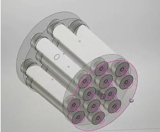
1. Power Density Through Superior Heat Transfer
Liquid cooling (typically deionized water or 50/50 water-glycol) delivers thermal conductivity 25x higher than forced air. This isn’t theoretical—it translates to:
- 5–10x power density: A 100 kW liquid-cooled unit occupies the same footprint as a 10–20 kW air-cooled bank
- Stable junction temperatures: Maintaining resistive elements at <80°C even under continuous full load
- Predictable thermal resistance (Rth): Typically 0.05–0.1 °C/W for liquid-cooled vs. 0.5–1.0 °C/W for air-cooled designs
2. The Damping Resistor’s Role in Filter Stability
In a typical single-tuned PHF, the damping resistor (R) serves two critical functions:
Resonance Control: Without damping, L-C circuits exhibit high Q-factors, creating sharp impedance peaks that can amplify non-target harmonics. The resistor broadens the frequency response, preventing unintended resonance amplification.
Energy Dissipation: Harmonic currents flowing through the filter branch generate I²R losses. In a 480V system filtering 200A of 5th harmonic current through a 2Ω damping resistor, power dissipation reaches 80 kW continuously.
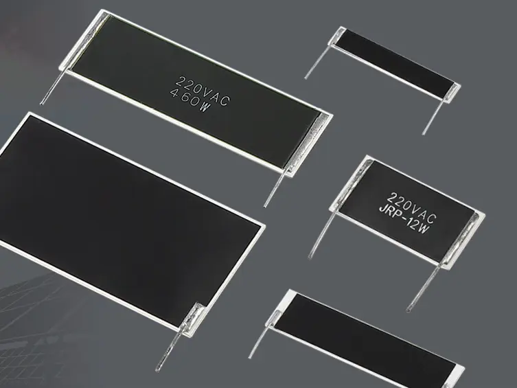
3. Material Science Considerations
Liquid-cooled resistors for PHF applications typically use:
- Stainless steel alloys (304/316): TCR ≈ +900 ppm/°C, but acceptable when temperature-stabilized by cooling
- Nickel-chromium alloys: TCR ≈ ±50 ppm/°C, preferred for precision applications
- Silicon carbide (SiC) ceramics: For ultra-high voltage (>10 kV) and pulse applications, offering TCR < ±200 ppm/°C
Critical specification: Dielectric strength of coolant path must exceed 1 MΩ·cm to prevent leakage currents, with periodic conductivity monitoring.
Integration with Existing Liquid-Cooled Infrastructure
For facilities already deploying liquid cooling—such as data centers using rack-mounted liquid-cooled dummy loads—integrating PHF damping resistors into the same cooling loop offers compelling advantages:
- Reduced capital cost: Leverage existing CDUs (Coolant Distribution Units), pumps, and heat exchangers
- Simplified maintenance: Single coolant chemistry (inhibited glycol) for all liquid-cooled equipment
- Unified monitoring: Temperature, flow rate, and pressure sensors tie into existing DCIM/BMS platforms
Practical Example: A 2 MW data center with 380V DC distribution and 48V server racks can integrate:
- Rack-level liquid-cooled loads for PSU testing
- PDU-level PHFs with liquid-cooled damping resistors (targeting 5th/7th harmonics from rectifier switching)
- Both subsystems sharing a 10 GPM coolant loop at 40°C inlet temperature
Design Challenges and Solutions
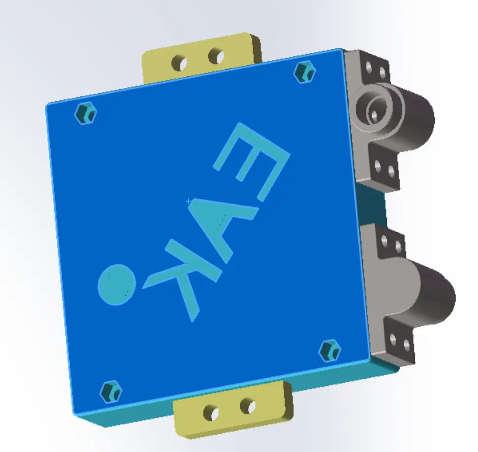
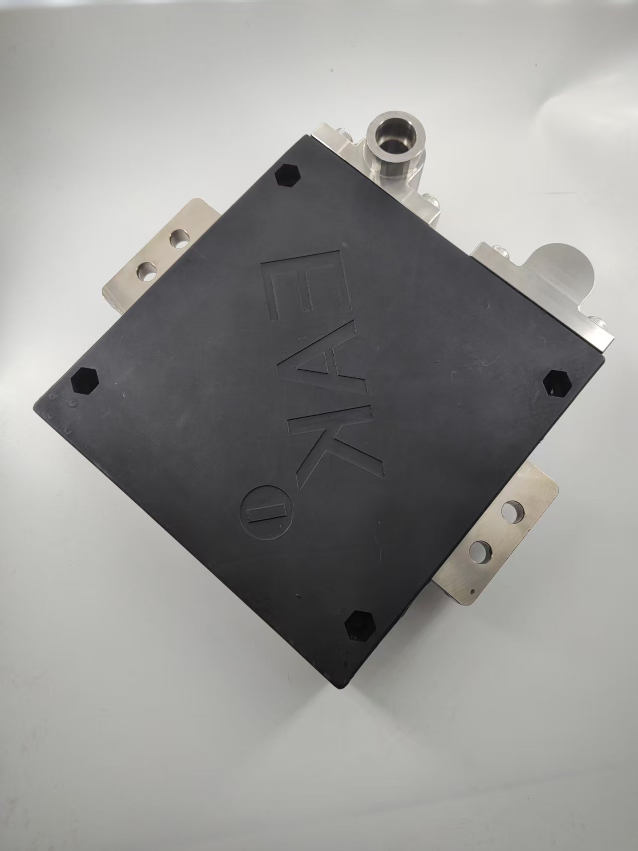
Challenge 1: Electrical Isolation Under Pressure
Problem: Coolant operates at 60–100 PSI; any seal failure risks short circuits.
Solution: Double-wall heat exchanger design with intermediate air gap. If primary seal fails, coolant vents to atmosphere before contacting electrical elements. Pressure differential monitoring triggers alarms at ±5 PSI deviation.
Challenge 2: Thermal Inertia vs. Transient Response
Problem: Liquid systems have higher thermal mass, potentially allowing temperature spikes during sudden harmonic surges (e.g., motor starting).
Solution: Oversize the resistive element by 20–30% to handle 10-second transients without coolant flow adjustment. Use real-time thermocouples (PT100/PT1000) embedded in resistor body for predictive load shedding.
Challenge 3: Long-Term Coolant Degradation
Problem: Glycol oxidation at elevated temperatures (>80°C) can form acidic byproducts, attacking metals.
Solution: Maintain coolant pH 8.0–9.0 with inhibitor packages (typically molybdate or sebacate). Replace coolant every 3–5 years or when conductivity exceeds 5 µS/cm.
Application-Specific Design Examples
Data Center HVDC Distribution (380V DC)
Harmonic Profile: Predominantly 5th/7th/11th from three-phase rectifiers feeding DC bus.
Filter Design:
- 5th harmonic: L = 2.5 mH, C = 400 µF, R_damp = 2.2 Ω (liquid-cooled, 120 kW rating)
- Coolant: 50/50 water-glycol, 8 GPM flow rate
- Enclosure: NEMA 3R outdoor-rated stainless steel, IP65
Measured Results: THDi reduced from 42% to 8%, meeting IEEE 519 limits at PCC.
Industrial VFD (6-pulse, 690V AC, 2 MW)
Harmonic Profile: 5th (20%) and 7th (14%) dominate; 11th/13th at 6–8%.
Filter Design:
- 5th: R_damp = 4.7 Ω, 180 kW continuous, 270 kW for 10 seconds
- Coolant integration: Shared loop with VFD liquid-cooled IGBTs
- Safety: Redundant flow switches; automatic bypass if flow drops below 6 GPM
Operational Note: Filter reduced upstream transformer heating by 18%, extending transformer life by an estimated 5 years.
Solar Farm Grid Interface (2.5 MVA Inverter)
Harmonic Profile: High-frequency switching harmonics (2–5 kHz) from SiC-based inverters.
Filter Design:
- High-pass filter (3rd order): R_damp = 8.2 Ω (ceramic SiC construction)
- Liquid-cooled due to outdoor ambient temps up to 50°C (122°F)
- Compliant with: IEEE 1547, IEC 61000-3-6
Performance Validation & Testing Standards
Qualified liquid-cooled PHF resistors should meet:
- IEC 60115-1: Generic specification for fixed resistors
- UL 508: Industrial control equipment (for enclosure/cooling system)
- Pressure testing: Hydrostatic test to 1.5x operating pressure (typically 150 PSI)
- Thermal cycling: 100 cycles from 20°C to max rated temp with <2% resistance shift
- Dielectric strength: 3.5 kV AC (1 minute) between resistive element and coolant jacket
Cost-Benefit Analysis: Liquid vs. Air Cooling
| Parameter | Air-Cooled Bank | Liquid-Cooled Unit |
|---|---|---|
| Initial Cost (100 kW, 3Ω) | $12,000 | $28,000 |
| Footprint | 2.1 m² | 0.4 m² |
| Noise Level | 75 dBA (fans) | 40 dBA (pumps) |
| Maintenance (annual) | $800 (filter cleaning) | $400 (coolant check) |
| Failure Rate (10 yr) | 8–12% (thermal stress) | 2–4% (seal/pump) |
| Energy Efficiency | 5% fan power overhead | 2% pump power overhead |
ROI Calculation: For a 24/7 data center application, liquid cooling pays back in 3.2 years through:
- Reduced HVAC load (fan heat removal)
- Lower failure-related downtime costs
- Space savings enabling additional revenue-generating equipment
Future Trends: Smart Liquid-Cooled PHFs
Emerging developments include:
- Adaptive damping: Real-time resistance adjustment via semiconductor switches to optimize Q-factor across load conditions
- Predictive maintenance: Machine learning models analyzing coolant temp/flow/conductivity trends to forecast seal failures 30–60 days in advance
- Wide-bandgap integration: SiC/GaN resistive elements enabling operation at 150°C coolant temps, unlocking waste heat recovery for building HVAC
Conclusion: Engineering Beyond the Spec Sheet
Specifying liquid-cooled resistors for passive harmonic filters isn’t simply a thermal management decision—it’s a system-level reliability investment. In applications where harmonic mitigation is mission-critical (medical imaging, semiconductor fabs, Tier III+ data centers), the superior power density, thermal stability, and failure mode safety of liquid cooling justify the initial cost premium.
For engineers designing next-generation power distribution systems, the question isn’t “Can we afford liquid cooling?” but rather “Can we afford the downtime, derating, and floor space waste of not using it?”
Engineering Support: Request thermal simulation data (CFD/FEA), coolant compatibility charts, and custom filter design assistance from EAK’s application engineering team.